
Total Knee Replacement
Total knee replacement is considered one of the most successful of all orthopedic surgeries. Complications of the patello-femoral joint, however, involve as many as 12% of all cases and remain one of the principal causes for revision surgery.Altered patella tracking has been identified as a major cause for this failure, and for this reason the Orthopedic Research Institute in Wichita, KS had initiated an in-depth study of the musculo-skeletal anatomy and biomechanics that underlie these problems.
The objective of this study was to determine a method for incorporating the degree of femoral anteversion and quadriceps angle into the alignment procedure of the femoral component during total knee arthroplasty. Based on these analyses, new guidelines and procedures for surgical alignment are being developed.
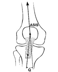
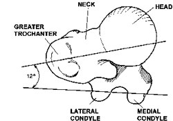
Below are two images that show how the q-angle and the femoral anteversion are generally measured.
|
|
Q-angle and FNTA
The femoral neck torsion angle (FNTA) is the angle between the axis of the femoral neck (cervical plane) and the coronal plane of the femoral condyles (condylar plane). If the neck is oriented forward with respect to the condylar plane, it is referred to as anteversion (positive FNTA).
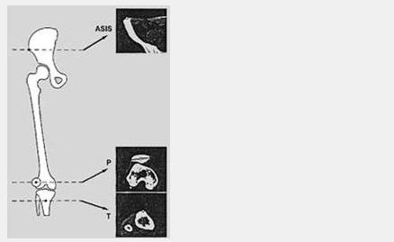
Patella Tracking Study -
Re-alignment after total knee replacement
My Thesis
I participated in the study as part of my final technical college thesis. The main goal was to find the correlation between anatomic landmarks (like the Q-muscle angle) and long term problems seen in patients that received a total knee replacement. In order to simulate effects of potentially incorrect anatomical geometry, CT data sets were converted and further processed in CAD and FEA programs, before being used to simulate stress loads and motions of various knee surfaces.Below are some images showing a few conversion steps from CT slice scans to a three-dimensional CAD model.
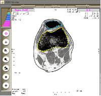
This shows the tracing software at work.
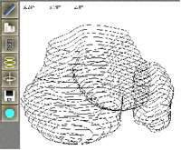
Here you see the wireframe CAD model of my knee.
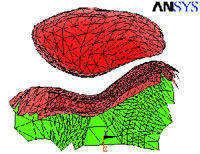
To the right is the final model of femoral groove and patella with assigned properties and all boundary conditions.
More to the study, the methods used and the Finite Element Analysis (FEA) in the info section below.